

The Authority in Global Agricultural Chemistry & Bio-Resources
Energy-Efficient Aquaculture Planning: Reducing RAS Pumping and Aeration Costs
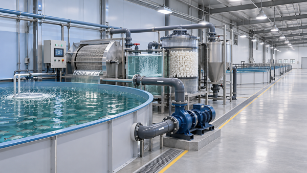
Pumping and aeration are among the most significant operating costs in recirculating aquaculture systems (RAS), making energy efficiency a design decision rather than an equipment upgrade to consider later. Good planning balances hydraulic requirements, oxygen delivery, fish welfare and capital expenditure against long-term operating performance. The challenge is not simply to use less power: it is to deliver the right water quality through changing biomass, feeding rates and equipment conditions, including when something fails.
Start with the production load, not the pump catalogue
A RAS design usually begins with a target harvest volume, but pumps and oxygen systems do not experience the farm as an annual average. They experience a daily and seasonal load shaped by stocking schedules, fish size, feed input, water temperature and operating practices. A project designed only around an average condition can struggle at peak biomass; one sized entirely around a conservative peak can waste energy for much of the production cycle.
Build a load profile before comparing equipment. At minimum, define expected and peak recirculation flow, oxygen demand, carbon dioxide removal, solids loading and temperature-control requirements. Include cleaning cycles, filter fouling and maintenance periods. The flow needed for solids transport or biofilter performance may be different from the flow needed to supply oxygen, so each constraint should be visible in the design basis.
For a phased development, distinguish between the equipment required on opening day and the capacity needed at full build-out. Installing all pumps and blowers at once may simplify construction, but running oversized equipment during an extended ramp-up can be expensive. A modular arrangement can provide a better fit, provided the partial-load hydraulic layout and control strategy are designed properly.
Draw the water path before calculating the electricity bill
The most efficient pump cannot compensate for an unnecessarily demanding system. Map the water path from fish tanks through solids removal, biological treatment, gas management and back to the tanks. Mark every lift, pressure requirement and likely restriction. Then ask which components truly need to be elevated or pressurised and where gravity flow is practical.
The essential distinction is between static head, associated with elevation or pressure differences, and friction losses through pipework and equipment. A long, undersized pipe, a dense cluster of fittings or a filter operated near its fouling limit can add head that the pump must overcome continuously. In a closed or partially closed arrangement, do not assume every elevation change adds directly to pump head; the actual hydraulic boundary conditions matter.
Allowing more space for larger pipes or a different equipment layout can reduce operating demand, but it also raises material and installation costs. Compare the alternatives using the expected hours of operation and tariff, not pipe price alone. Also check minimum velocities and cleaning arrangements: a pipe selected only to reduce friction may create solids-settling problems elsewhere.
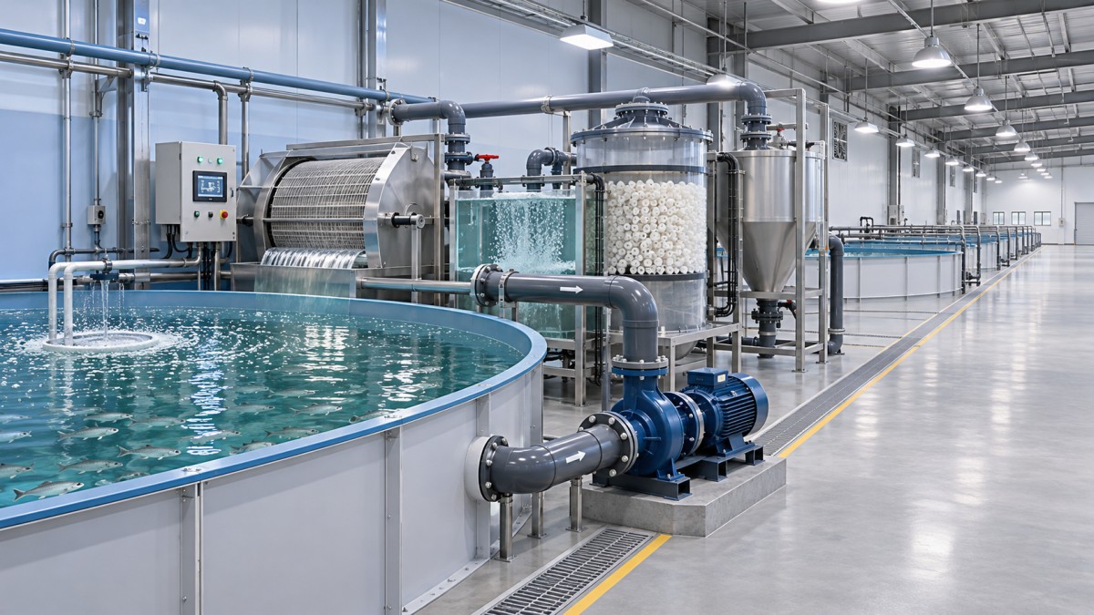
A useful design review traces the system curve under both clean and fouled conditions. That exercise often exposes a familiar problem: safety allowances have been added separately by the tank designer, filter supplier and pump supplier. The resulting pump may be much larger than the system needs. Keep a documented allowance for uncertainty, but avoid counting the same uncertainty several times.
Select pumps for the operating window
Compare pump curves with the system curve at the expected operating points, not just at a single maximum duty. Review efficiency, flow and head together, and include motor, drive and transmission losses when estimating electrical input. A pump that looks attractive at its best-efficiency point may spend most of its life far from it.
Parallel pumps can help match capacity to production stages and provide redundancy. Their combined performance, however, must be checked against the shared system curve; adding a second pump does not necessarily double flow. Confirm how pumps will be sequenced, whether standby units can be isolated and maintained, and what happens to flow when one unit stops.
Variable-frequency drives can reduce energy use when flow genuinely needs to vary, particularly where friction losses dominate. They are not an automatic saving. High static head, minimum flow requirements and control losses can limit the benefit. Avoid using a drive to disguise a poor initial equipment selection, and verify that the proposed speed range remains acceptable for the pump, motor and water-treatment process.
Throttling a permanently oversized pump is another warning sign. A partly closed valve may produce the desired flow, but the system is deliberately dissipating pressure that was paid for electrically. There can be sound control reasons for a valve, yet persistent throttling should trigger a review of impeller size, pump selection or operating sequence.
Treat oxygen supply and carbon dioxide removal as linked decisions
Aeration, oxygenation and degassing serve related but different purposes. Aeration may transfer oxygen and help remove carbon dioxide; dedicated oxygen injection can deliver oxygen without providing the same degree of carbon dioxide removal. Choosing an oxygen system solely because it reduces blower power can leave an expensive gas-management problem elsewhere in the process.
Compare alternatives at the actual water quality and production conditions. Oxygen transfer depends on factors including contact time, pressure, temperature, salinity, existing dissolved oxygen and equipment configuration. A supplier’s transfer figure is useful only when its test conditions and measurement boundary are understood. Ask what electrical demand, oxygen supply and pressure loss are included, and what must be provided by other equipment.
For example, a pressurised oxygen contactor may reduce the amount of undissolved oxygen leaving the device, but its pressure requirement can increase pumping energy. An on-site oxygen generator adds electrical load and maintenance; purchased liquid oxygen introduces delivery, storage and supply-continuity considerations. Neither option can be judged from the blower or pump nameplate alone.
Keep fish welfare at the centre of control decisions. Dissolved oxygen setpoints and alarm limits should be established for the species, life stage and operating conditions, with input from the fish-health and process teams. Reducing air or oxygen delivery may appear to save power while shrinking the response time available after a sensor fault, feeding event or equipment trip.
Make controls earn their place
Controls are most useful when they respond to a meaningful process requirement. Dissolved oxygen sensors can regulate oxygen delivery, while flow and differential-pressure measurements can reveal changes in hydraulic resistance. Trend data is often more informative than a single reading: a gradual rise in filter differential pressure, for instance, may explain a pump’s increasing power draw before operators see a more obvious process problem.
Instrumentation also creates failure modes. Sensors foul, drift and occasionally disagree. Specify cleaning access, calibration procedures, alarm response and a safe fallback mode. A dissolved oxygen probe mounted where water is poorly mixed may give a reassuring reading while another part of a tank is under stress. Sensor placement deserves the same attention as sensor selection.
Submeter the major electrical loads if the project budget permits: recirculation pumps, blowers, oxygen generation and temperature control should be distinguishable where practical. Without that separation, an apparently efficient design can be difficult to troubleshoot, and the effect of a control change may be hidden in the site-wide electricity bill.
Compare lifetime cost without hiding the assumptions
A credible energy comparison begins with operating scenarios. Estimate electrical input at each expected duty point, multiply by the hours spent there and apply a tariff that reflects the site’s expected charges. Where demand charges or time-dependent prices apply, annual kilowatt-hours alone will not describe the whole bill. Include oxygen purchases, routine maintenance, replacement parts and any extra building or pipework costs that differ between options.
Keep backup equipment in the comparison, even if it normally consumes little energy. A design with no practical maintenance window or inadequate standby capacity is not equivalent to one that can sustain fish during a foreseeable failure. Check power outage duration, backup power start-up, stored oxygen availability and the time operators need to respond. The right level of redundancy depends on biomass, site access and the consequences of interruption.
Run the economics again with less favourable assumptions: lower production, a longer ramp-up, higher electricity prices or more frequent maintenance. If the preferred option changes easily, present that sensitivity to the investment team rather than presenting one precise-looking payback figure. Energy efficient aquaculture planning is strongest when the engineering and commercial assumptions can be examined together.
Protect the design through procurement and commissioning
Tender documents should state the duty points, water characteristics, allowable pressure losses, operating envelope and required control modes. Ask suppliers to identify exclusions and provide performance curves rather than a single headline efficiency. Interfaces matter: a filter supplier’s assumed inlet pressure, for example, must agree with the pump supplier’s design basis.
For cross-border projects, confirm electrical compatibility, service access, spare-parts availability and applicable local environmental and safety requirements before equipment is ordered. AgriChem Chronicle’s broader focus on primary processing and industrial supply chains is relevant here: an efficient component is of limited value if its consumables or specialist support cannot be obtained reliably at the farm.
During commissioning, measure flow, pressure, power and dissolved oxygen at agreed operating conditions, and compare results with the design basis. Test duty changes, sensor faults and standby changeover as well as normal operation. Record any temporary valve positions or manual overrides; these can quietly become permanent and undermine the original energy calculation.
Before approving the final design, ask for one drawing and one operating table that show where water is lifted, where pressure is lost, which equipment runs at each production stage and how the system responds to a failure. If those answers are unclear, there is still work to do before the project can make a defensible claim about its future pumping and aeration costs.
Related Intelligence
- RAS SystemsEnergy-Efficient Aquaculture Planning: Reducing RAS Pumping and Aeration CostsEnergy efficient aquaculture planning can reduce RAS pumping and aeration costs. Explore practical design strategies that protect fish welfare and improve long-term performance.
- RAS SystemsPhilippine Black Tiger Shrimp Revival Plan Yields 3.65 TonnesPhilippine black tiger shrimp revival yields 3.65 tonnes in an Iloilo research cycle. Explore survival rates, feed efficiency and potential sourcing implications.
- RAS SystemsRAS vs. Flow-Through Aquaculture: What Are the Key Differences?What are the key differences between RAS and flow through aquaculture? Compare water use, costs, biosecurity, and operational risks to find the right system for your farm.
The Morning Broadsheet
Daily chemical briefings, market shifts, and peer-reviewed summaries delivered to your terminal.